
REGDOC-2.5.5: Design of Industrial Radiography Installations
Preface
This regulatory document is part of the CNSC's Physical Design series of regulatory documents, which also covers: design of uranium mines and mills, reactor facilities, nuclear substance laboratories, and nuclear medicine rooms. The full list of regulatory document series is included at the end of this document and can also be found on the CNSC’s website.
Industrial radiography involves the use of risk-significant sealed sources of nuclear substances, most commonly cobalt-60, iridium-192 and selenium-75, to evaluate the internal structure and integrity of metals and other materials in pipelines, welds, castings and building structures.
A radiography installation is any shielded enclosure, cell or vault where radiography is performed. These shielded enclosures can be very effective in preventing or minimizing doses to both operators and persons within the vicinity. Radiography installations can also provide an additional level of safety by preventing unauthorized access during operations.
REGDOC-2.5.5, Design of Industrial Radiography Installations, provides guidance for the design of radiography installations. This information will assist individuals in the design and construction of installations that are safe to use, and that ensure that doses to certified exposure device operators, workers and all persons in the vicinity of the work being performed are within regulatory limits and are kept as low as reasonably achievable.
Table of Contents
1. Introduction
Industrial radiography is a non-destructive method of looking for defects in materials by examining the structures of welds, castings, and building components. Certified personnel use high-activity sealed nuclear substances in certified exposure devices.
Industrial radiography operations take place in a variety of locations and under different environmental conditions. Work is done inside buildings under controlled conditions and is also carried out in the field in adverse weather. Licensees must ensure that effective measures are in place to limit the radiation exposure to any person as a result of radiography operations wherever they are conducted.
Whenever possible, industrial radiography equipment should be used inside an industrial radiography installation, to protect workers and minimize radiation exposure to any other person.
Whether a radiography installation is temporarily or permanently installed, all of the design principles described in the following sections apply. This is to ensure that the radiography installation performs as expected and provides the necessary level of safety to control radiation exposures. All CNSC regulatory requirements, including those specific to radiography, apply to all uses of nuclear substances and radiation devices within a radiography installation.
Radiography installations must comply with all applicable national, provincial/territorial and municipal safety codes, including those for building and fire protection. The guidance provided in this regulatory document does not supersede the requirements of any permitting authority.
1.1 Purpose
This regulatory document provides guidance for the design of an industrial radiography installation.
1.2 Scope
The guidance provided applies to the design of industrial radiography installations for the use of sealed nuclear substances, including fixed (permanent) and temporary structures, and installations not under the direct control of the certified person(s) conducting the radiography operations.
This document does not apply to the design of installations for:
- the use of sealed nuclear substances regulated under the Class II Nuclear Facilities and Prescribed Equipment Regulations
- neutron radiography
The provinces and territories regulate the use of x-ray generators for industrial radiography. The design of installations for their use is outside the scope of this document.
REGDOC-2.5.5 addresses design features that enhance nuclear safety and security. Other health, safety, and environmental considerations may dictate adherence to additional guiding principles.
1.3 Relevant legislation
The following regulations made under the Nuclear Safety and Control Act are relevant to this document:
- Paragraph 12(1)(c) of the General Nuclear Safety and Control Regulations: "Every licensee shall ...
- (c) take all reasonable precautions to protect the environment and safety of persons and to maintain the security of nuclear facilities and of nuclear substances; ...”
- Paragraph 3(1)(d) of the Nuclear Substances and Radiation Devices Regulations (NSRD Regulations) states: "An application for a licence in respect of a nuclear substance or a radiation device, other than a licence to service a radiation device, shall contain ... (d) the proposed location of the activity to be licensed, including a description of the site."
- Section 24 of the NSRD Regulations states "No person other than a certified exposure device operator, or a trainee who is acting under the direct supervision and continuous observation of a certified exposure device operator, shall operate an exposure device.
- Subsection 30(6) of the NSRD Regulations states: "Every licensee shall limit the dose of radiation received by a person, other than a nuclear energy worker, as a result of the possession or use of an exposure device to 0.1 mSv per week and 0.5 mSv per year."
- Paragraphs 31(1)(i),(j) and (k) of the NSRD Regulations states: "Every person who operates an exposure device shall ...
- (i) limit the dose of radiation received by any person, other than a nuclear energy worker, as a result of the possession or use of the exposure device to 0.1 mSv per week and 0.5 mSv per year;
- (j) place persons or erect barriers to prevent entry into any area within which the radiation dose rate is greater than 0.1 mSv per hour as a result of the possession or use of the exposure device;
- (k) post a sufficient number of durable and legible signs that bear the radiation warning symbol set out in Schedule 3 to the Radiation Protection Regulations and the words "RAYONNEMENT – DANGER – RADIATION", to prevent entry into any area within which the radiation dose rate is greater than 0.1 mSv per hour as a result of the possession or use of the exposure device."
- Section 4 of the Radiation Protection Regulations states: "Every licensee shall implement a radiation protection program and shall, as part of that program,
- (a) keep the amount of exposure to radon progeny and the effective dose and equivalent dose received by and committed to persons as low as is reasonably achievable, social and economic factors being taken into account, through the implementation of
- management control over work practices,
- personnel qualification and training,
- control of occupational and public exposure to radiation, and
- planning for unusual situations; and
- (b) ascertain the quantity and concentration of any nuclear substance released as a result of the licensed activity
- by direct measurement as a result of monitoring, or
- if the time and resources required for direct measurement as a result of monitoring outweigh the usefulness of ascertaining the quantity and concentration using that method, by estimating them.
- (a) keep the amount of exposure to radon progeny and the effective dose and equivalent dose received by and committed to persons as low as is reasonably achievable, social and economic factors being taken into account, through the implementation of
- Section 21 of the Radiation Protection Regulations states: Every licensee shall post and keep posted, at the boundary of and at every point of access to an area, room or enclosure, a durable and legible sign that bears the radiation warning symbol set out in Schedule 3 and the words "RAYONNEMENT – DANGER – RADIATION", if
- (a) there is a radioactive nuclear substance in a quantity greater than 100 times its exemption quantity in the area, room or enclosure; or
- (b) there is a reasonable probability that a person in the area, room or enclosure will be exposed to an effective dose rate greater than 25 µSv/h.
2. General Design Principles
Design principles for industrial radiography installations are based on the requirement that all exposure device operators and licensees must ensure that any radiation exposures as a result of radiography operations remain within the limits set out in the regulations under the Nuclear Safety and Control Act. In addition, every effort must be made to further reduce exposures and doses to as low as reasonably achievable (ALARA), as required by subsection 4(a) of the Radiation Protection Regulations. For more information on ALARA, see CNSC regulatory document G-129 rev. 1, Keeping Radiation Exposure and Doses "As Low as Reasonably Achievable (ALARA)" [1]. Both licensees and certified exposure device operators (CEDOs) are required to limit the exposure of any person, other than a nuclear energy worker (NEW), to 0.1 mSv per week and 0.5 mSv per year.
The design of a radiography installation includes the consideration of factors besides those obviously associated with minimizing radiation exposure. All relevant factors, including workload, structural, accessibility and economic should be considered at the design phase of the radiography installation. Evaluation of these factors will contribute to ensuring that the final product is effective and can be readily and safely used by CEDOs, while also providing the necessary protection for any other person in the vicinity of radiography operations. These factors should be evaluated for the immediate and the foreseeable future needs of the persons using the installation.
There are two methods to minimize radiation exposure: the application of engineered controls (e.g., shielding material, location) and the application of administrative controls (e.g., limiting nuclear substance sealed source activity, restricting access and time in proximity to the installation). The design of a radiography installation should give preference to the use of engineered controls where ever possible, which are always functional. Administrative controls, which have to be constantly applied, can be used as supplemental controls when engineered controls are not sufficient or applicable. For example, establishing a permanent exclusion zone by design is preferred to establishing a barrier system that has to be monitored by one or more persons.
Engineered controls include:
- radiation exposure controls
- distance
- shielding
- skyshine
- structural considerations
- walls, roof, doors/access
- floor
- services (electrical, water, sewer, pneumatic, hydraulic, etc.)
- openings and penetrations
- accessibility
- size and weight of exposure devices
- size and shape of materials for examination
- security measures
Administrative controls include:
- placing limits on nuclear substance type and activity
- restricting use of areas adjacent to the radiography installation
- adjusting workload (including time of day considerations)
- controlling occupancy of surrounding areas
- limiting the position and direction of the source within the installation
- monitoring for human presence prior to exposures
The radiography installation owner should ensure that appropriate safety signs, notices, barriers and associated documentation regarding any administrative controls are available to all persons who will need to know the specific safety limits imposed, including operators using the installation and any other person who may enter the area.
3. Engineered Controls
The design of the radiography installation should incorporate the following engineered controls to ensure that the prescribed exposure limits will be respected and that all exposures are kept consistent with the ALARA principle.
3.1 Radiation exposure controls
3.1.1 Distance
Changing the distance between the radiation source and the position of the radiation detector will result in large changes to the radiation exposure as it is inversely proportional to the square of the distance from the source. For example, with other variables constant, doubling the distance from the source of radiation will result in a reduction of radiation dose by a factor of four. When considering design and placement, industrial radiography installations should be located as far as possible from workspaces and places that could reasonably be expected to be occupied when radiography would take place.
The design of the installation should also facilitate the ability to use the full length of the control cable for each exposure device being used and should not compromise or restrict the use of long-handled tools that may be needed to respond to emergencies, such as source recovery operations.
3.1.2 Shielding
The use of shielding around the radiation source will reduce radiation exposures and consequently any resulting radiation doses. Generally, for any given material, the thicker the shielding placed between the person and the source, the lower the exposure to radiation for that person. The choice of shielding depends on the quantity and energy of the radiation to be shielded and generally involves structural and economic considerations. The nuclear substances used for industrial radiography emit high-energy gamma radiation, so these nuclear substances require significant thicknesses of lead and/or concrete to reduce the radiation levels to acceptable levels.
The shielding for a radiography installation should be designed based on the anticipated maximum activity of each nuclear substance that is to be used in the installation.
For any given nuclear substance, the relationship between radiation dose and the activity of the source is directly proportional and this is represented by the value known as the gamma ray constant.
Table 1 provides gamma ray constant values in microsieverts per hour (µSv/h)at 1 metre per gigabecquerel (GBq) of activity of an isotope. These values are derived from Conversion Coefficients for Radiological Protection Quantities for External Radiation Exposures [2] published by the International Commission on Radiological Protection and the Joint Evaluated Fission and Fusion File (JEFF) 3.1 published by Nucleonica GmbH [3].
| Nuclear substance | Gamma ray constant value (µSv/h per GBq at 1 m) |
|---|---|
| Cobalt-60 | 305 |
| Iridium-192 | 117 |
| Cesium-137 | 78 |
| Selenium-75 | 56 |
| Ytterbium-169 | 52 |
The gamma ray constant and the known activity of the nuclear substance can be used to calculate the potential radiation exposure to persons in the vicinity of the nuclear substance. For example, it is possible to determine that a 10 GBq sealed source of Ir-192 will result in an effective dose rate of 1170 µSv/h (or 1.17 mSv/h) at 1 metre from the sealed source. Corrections must be applied for changes to distance and the introduction of any shielding between the source and the location of measurement. Exposures at other distances from the sealed source can be calculated by use of the inverse-square law equationFootnote 1.
Higher-energy gamma sources (such as cobalt-60) will require more shielding than lower-energy gamma sources (such as selenium-75). Similarly, higher quantities of a particular nuclear substance will require larger amounts of shielding to reduce the dose rate to the same level as a smaller quantity of that same nuclear substance.
Lead and concrete are effective shielding for reducing dose rates associated with the gamma radiation emitted by sealed sources used in industrial radiography. Whichever type of shielding is used, it should be made of solid material with no cracks, holes or voids.
If blocks of shielding are used, they should be arranged to avoid spaces or voids between the blocks. Any gaps, voids or spaces between shielding blocks should be filled with a sufficient quantity of similar or better shielding to ensure that the shielding is effective. If two or more walls of lead or concrete shielding blocks are used, the joints should be offset to minimize a direct path for the radiation through the joints in the walls. When sheets of lead shielding are used in walls, the lead sheet should be properly supported, to ensure that it does not displace or move from the original installation, since lead will tend to sag or creep over time.
Since radiation travels in all directions, shielding should be considered for all adjacent areas, including above and below the radiography installation, as applicable.
If the design does not or cannot provide enough shielding to meet the dose rate limit of 0.1 mSv/week or 0.5 mSv/year, as well as demonstrate adherence to the ALARA principle, additional administrative controls, such as a larger exclusion zone, will have to be established and enforced during radiography operations. See G-129 rev 1, Keeping Radiation Doses "As Low as Reasonably Achievable (ALARA)" [1] for guidance on the ALARA principle.
Appendix A provides a method for calculating radiation exposures based on the design of the installation.
3.1.3 Skyshine
Skyshine can be a significant source for radiation exposure when large sealed sources are used without overhead shielding. Skyshine is radiation that is emitted upwards from inside of an installation and then reflected back down by air (see figure 1). In general, radiography installations should be designed with a shielded roof to minimize skyshine and reduce occupational exposure to workers and other persons.
Figure 1: Radiation emitted as skyshine
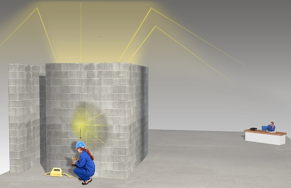
Maximum dose rates from skyshine may not occur immediately adjacent to the shielded wall, but may reach a distance from that wall and could also reach any elevated workstations that surround the installation.
When an installation has minimal (for example, to protect against the weather) or no roof shielding, the design should take into account the potential for radiation exposure due to skyshine.
When skyshine is a significant source of radiation exposure, the design of the roof will have to include a sufficient amount of effective shielding. In such cases, the design of the installation will have to incorporate an appropriate supporting structure for the additional weight of the shielding on the roof.
If exposure to skyshine is significant, but it is impractical to install or shield a roof, access to adjacent areas should be limited or prevented through the use of engineered controls (e.g., radiation warning monitors), administrative controls (e.g., limited access to the area) or a combination of both.
Evaluation of the potential for skyshine from a radiography installation is a complex calculation and the owner is encouraged to seek professional assistance from a person who has the necessary experience and knowledge to competently carry out this work.
3.2 Structural considerations
3.2.1 Walls, floors, roof, and doors
As with any construction, structural considerations should be taken into account at the time of design, and reassessed regularly during construction and operation of the installation. Since radiography installations typically involve the use of substantial quantities of heavy materials such as shielding, the radiography installation should be designed and operated with structural considerations in mind. This includes, but is not limited to:
- walls that are self-supporting, contiguous and will not topple
- walls and supports with a sufficient base to ensure that there is no sag, slump or other deterioration caused by settling of the ground
- supports or foundations that are properly protected against the effects of frost heave or freezing of the ground
- floors with sufficient capacity to manage the static and dynamic loads that will be imposed by the weight of the required shielding for walls and supporting requirements for the roof
- doors that contain shielding are easily and safely moved by one person from either side
- entrances of sufficient width and height to accommodate persons and equipment
- a roof with adequate support for the required shielding and other loads
- sufficient setback from property and building lines to ensure access for servicing adjacent areas
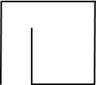
Personnel access and equipment doorways in the shielding of the radiography installation should not compromise the shielding provided by the walls. This may require the use of a sufficiently shielded door. However, if radiation from the exposure device is in a direct line to the door, the necessary shielding for the door may make it too heavy or unwieldy to operate safely. Whenever possible, the entry to a radiography installation should be designed with an indirect pathway to the area where radiography will be conducted, also known as a "maze entrance" (see figure 2). The use of a maze entrance minimizes any radiation leaks through the entrance to the radiography installation, and also may reduce the need for the use of heavy, thick concrete or lead in the door to the radiography installation. Furthermore, the use of a maze entrance reduces the amount of radiation that may escape the radiography installation when the exposure device operator needs to access the radiography device.
The potential for scatter radiation at a maze entrance should be evaluated to determine if additional protection, such as a shielded door, is required.
Figure 2: Radiography installation design with a maze entrance
The radiography installation must be designed, constructed and operated in accordance with all federal, provincial/territorial or municipal requirements for such structures. In particular, all applicable building and fire code requirements must be met.
3.2.2 Services
The design of the radiography installation should take into account current and future provision of services that may be required. These include:
- electrical wiring for:
- general and task lighting
- operation of exposure devices
- operation of other equipment
- data
- control systems
- alarm systems
- monitoring systems
- water:
- cold
- hot
- distilled or deionized
- sewage or waste
- air:
- HVAC
- compressed
- fuel:
- heaters
- operation of other equipment
3.2.3 Openings, penetrations and excavations
Where any service or other opening is required to provide access to the interior of the radiography installation, the design of the installation should ensure that the penetration through the shielding does not compromise the intended level of protection afforded by the shielding design. Any penetration through shielding should not be in a straight line directly through the shielding but should traverse the shielding in the form of either an arc or at an angle. Any penetration that must traverse the shielding in a straight line (such as HVAC ducting) should be located high on the shielding wall or otherwise located to prevent a potential for exposure to any person outside of the installation. Gaps around pipes or conduits should be filled with lead or concrete to minimize the diameter of penetrations where possible.
Where excavation is required to install a service line, the floor should be restored such that the repaired area will not compromise the structural integrity of the installation. Any excavations below the level of the floor should be refilled with material in sufficient quantity and density to provide the same or better structural support as the undisturbed floor.
In general, controls for the operation of industrial radiography equipment should be located on the exterior of the radiography installation. Such an arrangement will necessitate a penetration into the installation.
3.3 Accessibility
3.3.1 Size and weight of exposure devices
The design of the installation should account for the physical characteristics of the exposure device expected to be used. Because of their smaller size, devices that use iridium-192 and selenium-75 are less likely to require special design considerations than larger and heavier cobalt-60 exposure devices. If an exposure device is difficult to manipulate or move, the design of the installation should include measures such as wider corridors to allow for movement and turning of the device.
The installation design should also allow for radiation source changes, including the additional containers or other packages that may be required to undertake the source change. If it is not feasible or possible to remove the exposure device to change the sealed source, then the design of the installation should allow for a new source in a shielded container or other package to be brought into the installation, safely opened, and exchanged with the old source while minimizing potential exposures to any nearby person.
If it is not possible to design the installation to accommodate a variety of exposure devices that may be used, it may be necessary for the radiography installation owner to limit the nuclear substances used, the quantity of a specific isotope, or the size of the exposure device.
3.3.2 Size and shape of material for examination
Since the intent of radiography evaluations is to examine the structural integrity or arrangement of another item, the radiography installation should be designed for the entry and exit of the anticipated items for evaluation. This may include:
- designing an entrance which will allow for easy access by carts, forklifts or other conveyances
- providing overhead access capability to lift objects in and out of the radiography installation, including the provision of a suitable lift crane or hoist
- providing a special removable section of the wall or roof to allow for the infrequent entry and exit of such items while not compromising the intended shielding of the installation
- incorporating sufficient support for cranes or hoists required for moving large or heavy items for examination
3.4 Security measures
The exposure devices used inside radiography installations often contain high-risk Category 1 or 2 radioactive sealed sources. Although the radiography installation itself is not subject to requirements of REGDOC-2.12.3, Security of Nuclear Substances: Sealed Sources [4], it is recommended that the installation supplement security measures already integrated in the exposure device, by incorporating security-by-design concepts. In certain cases where a licensee uses an exposure device exclusively in a radiography installation, features of the installation may be used to achieve and demonstrate compliance with the requirements of REGDOC-2.12.3 (such as providing alarm systems or secure storage).
REGDOC-2.12.3 describes security-related regulatory requirements for the licensee’s security program for sealed nuclear substances, and provides general guidance to assist licensees on meeting these requirements.
Table 2 identifies best practices for achieving compliance by incorporating security-related features of the installation. These best practices assume that the radiography installation is not used for storage of exposure devices. If exposure devices are stored within the installation, additional requirements of REGDOC-2.12.3 apply. It is recognized that other design measures, already mentioned elsewhere in this document, are similar to those proposed in table 2.
| Security program subsection | Best practice in security by design |
|---|---|
| Access control |
|
| Intrusion detection system |
|
| Perimeter and/or physical barrier |
|
| Security of storage |
|
| Maintenance and testing |
|
| Installation security plan |
|
| Information security |
|
| Security awareness training |
|
4. Administrative Controls
Because administrative controls depend on persons to respect and adhere to them, they should supplement but not replace engineered controls.
4.1 Placing limits on nuclear substance type and maximum activity
Once the radiography installation has been designed for specific combinations of nuclear substances and maximum activity, the installation owner should restrict the use of nuclear substances there, so that limits are respected. Restrictions on the nuclear substances and/or the maximum activity of each nuclear substance to be used should be clearly posted on the exterior of the radiography installation.
4.2 Restricting use of areas adjacent to the radiography installation
Any room, area or enclosure adjacent to the radiography installation represents a potential location where unexpected radiation fields may exist with the potential for radiation exposure to other persons. The design of the radiography installation should consider all adjacent areas to ensure that any radiation exposures are within the prescribed limits and are kept consistent with the ALARA principle.
Areas adjacent to the radiography installation that should be considered include:
- below the installation (e.g., the basement)
- elevated around the installation (e.g., raised offices)
- above the installation (e.g., the roof, work areas on upper floors)
- on all sides of the installation on the same level
- neighbouring properties
The installation should be situated inside well-defined property boundaries at a sufficient distance from adjacent properties to allow for access to all parts of the installation and maintenance of the structure and shielding, as may be necessary.
All locations adjacent to the radiography installation should be clearly identified and marked on a plan of the installation to ensure that adequate consideration is given to reducing radiation exposures in these areas. These locations should include areas, rooms or enclosures used for storage or that are otherwise not normally occupied at the time of assessment. Since the usage and therefore the occupancy of such locations may change, the assessment should consider radiation exposure.
Based on the exposure potential for areas adjacent to the radiography installation, the CEDO should monitor exposures in these areas to ensure that radiation doses are not exceeded. Where the dose-rate in any area adjacent to the radiography installation exceeds the prescribed limit, posting of warning signs will also be required.
4.2.1 Adjusting workload
Workload should be determined using the most conservative assumptions at all times for all potential radiography work. The maximum workload needs to be determined on a weekly and annual basis.
Typically, the workload is expressed in the number of radiography exposures conducted on a weekly and annual basis and the anticipated maximum time for each exposure. Basing the workload on the anticipated maximum exposure time per exposure is an appropriate conservative assumption. Such information can be useful in the planning stages as well to ensure that the location has sufficient capacity to conduct all radiography operations safely.
Workload planning, for the purposes of ensuring sufficient capacity in a radiography installation, should also take into account the time required for exposure set up and tear down to ensure that there is sufficient time and capacity to conduct the required work.
If more than one radiography licensee uses a radiography installation, the design should take in to account the cumulative operations by all licensees.
The workload of a radiography installation may need to be restricted or otherwise limited to comply with the applicable radiation exposure limits.
4.2.2 Controlling occupancy of surrounding areas
The design should take into account the occupancy of surrounding areas by persons on both a full-time or temporary basis. Occupancy of areas in proximity to the radiography installation may change depending on the day or time of day. Furthermore, occupancy of surrounding areas may change on a seasonal basis where some adjacent locations are only used during certain months of the year.
The occupancy factor (T) for each location is the fraction of total time during which a radiation field is present at a particular location, for which any one individual would reasonably be expected to be present there. This factor (≤1) is multiplied by the total radiation dose at that location, to derive the maximum personal dose any single person would be expected to receive. Examples of occupancy factors are provided in table 3, which may be used as a guide in the absence of adequate occupancy data. The information provided is adapted from ANSI N43.3 2008, Installations Using Non-Medical X-Ray and Sealed Gamma Ray Sources, Energies Up To 10 MeV [5].
| Occupancy type | Examples | Occupancy factor (T) |
|---|---|---|
| Full occupancy | Control rooms, darkrooms, workrooms, shops, offices, and corridors large enough to be used as working areas, routinely used rest areas and lounges, living quarters, children’s play areas, occupied space in adjoining buildings | 1 |
| Partial occupancy | Frequently used corridors too narrow for desks, utility rooms, rest areas and lounge rooms not used routinely, elevators using operators, uncontrolled parking lots | 1/2 to 1/5 |
| Occasional occupancy | Infrequently used corridors, closets too small for future occupancy, toilets, stairways, automatic elevators, outside areas used only by pedestrians or vehicular traffic | 1/8 to 1/40 |
It is important to know typical work patterns for both radiographers in the installation and persons working in the vicinity. An ideal situation would be zero occupancy for areas around an installation when radiography is taking place. An example of this is scheduling radiography operations outside of normal working hours. While zero occupancy is ideal, it is rarely achievable. The person operating the exposure device should verify the occupancy of all adjacent areas before each exposure, and re-confirm that no persons have entered areas where the potential for a radiation exposure exists.
When designing the wall shielding, an occupancy factor of 1 should be assumed for any adjacent properties. Where the assessment has identified that locations adjacent to the radiography installation may be occupied, the design of the radiography installation should ensure that doses respect regulatory requirements through the use of additional shielding and other administrative or engineered control methods.
Where a radiography installation is located where the licensee or radiography installation owner has no control over occupancy of adjacent locations by any other person, design decisions should assume continuous occupancy of these locations to ensure that potential doses to such locations are within the prescribed regulatory limits and maintained ALARA.
As noted earlier, if shielding or other controls are not sufficient to reduce potential exposures below the prescribed limits, then restrictions should be placed on occupancy of areas adjacent to the radiography installation to ensure that no person exceeds the applicable exposure limits.
Appendix A provides a method for calculating radiation exposures based on the design of an installation. The example provided is for illustrative purposes only and demonstrates the type of information that may be required for this assessment.
4.2.3 Limiting the position and direction of the radiation source within the radiography installation
Generally there are no controls where radiography exposures can take place within a radiography installation. Therefore, radiation exposures outside of a radiography installation may increase or decrease depending on the distance between the sealed source and the shielding wall(s). Furthermore, changes in the direction of the radiation beam can also have a significant impact on the potential radiation exposures outside of a radiography installation.
When there is variability in position or direction of the beam, the design of the radiography installation should take these into account, and should be constructed for the configuration representing the highest potential exposure to any person outside of the installation. If it is not possible to reduce the radiation exposure outside of a radiography installation due to the variations, additional controls should be put in place to provide equivalent protection. These controls could include limiting the locations within the installation where radiography operations may be carried out.
4.3 Monitoring for human presence prior to exposures
In general practice, the CEDO conducting the radiography examination will be the last person to exit the radiography installation before exposing the nuclear substance. This is normally sufficient to ensure that the radiography installation is unoccupied. However, the CEDO should be positioned to ensure that no person can enter the radiography installation when the nuclear substance is in the unshielded position.
In accordance with the regulatory requirements, the CEDO must erect barriers or place persons to prevent anyone from entering the installation when a radiography exposure is being conducted. Therefore, the CEDO will need to evaluate the risks associated with any exposure and ensure that there are sufficient measures in place to prevent access to the installation during the exposure.
Remote monitoring of the interior of the radiography installation should be considered to ensure that no person is inside when the exposure operator is preparing to move the sealed source from the shielded position. Consideration should also be given to providing alarm or stop btns on the interior of the radiography installation to allow a person inside to signal other persons or cancel the planned exposure.
In all cases, the design of the radiography installation should include the provision of fire alarm or other emergency pull stations to summon aid or alert other persons of a potential fire or other emergency situation. Consultation with the applicable fire code provisions will establish the necessity for including any necessary alarm systems.
5. Construction
Any changes introduced during the construction due to unforeseen issues should be documented and included in the "as-built" drawings. All changes should be evaluated to ensure that they do not compromise the level of radiation protection and safety for which the radiography installation was designed.
If the radiography installation is going to be constructed inside an existing building or structure, the building or structure should have the structural capacity to allow safe construction and the eventual structural load of the radiography installation. In addition, the structural capacity must be sufficient for any dynamic or other loads introduced as a consequence of operating the radiography installation (for example, cranes, lifting machinery).
The construction of the radiography installation must not introduce deficiencies in the designed level of radiation protection. In particular, the shielding supplied must be of the composition, quality and quantity originally specified or better.
The following are examples of deficiencies that could be introduced:
- aggressive or rapid construction methods which compromise the shielding capability of the installation by the introduction of excessive voids in poured concrete
- hollow block walls not completely filled with mortar
- joints in shielding are not properly filled or finished
- lead shielding does not extend as specified in the plans
- unsupported lead sheeting
6. Commissioning
To determine if the installation meets design specifications, commissioning tests and radiation dose rate measurements should be performed prior to its use. If the testing shows that the installation does not adequately limit dose, additional shielding, safety, and security measures should be used.
Measurements should be taken to verify that there are no cracks, holes or voids in the walls, floors or ceiling which can result in localized areas of higher dose rates. Measurements should also be taken to confirm that the installed shielding is adequate and installed as originally designed and that any doses from skyshine are below dose limits and ALARA.
All radiation testing should be carried out with nuclear substances that are of the same type and quantity which are expected to be routinely used in the installation. Values of radiation doses for locations around the radiography installation should be calculated based on the nuclear substance and the activity used for the commissioning test. A method for calculating radiation doses based on the design of the installation may be found in appendix A. These expected values should be compared to actual observed radiation dose values to determine if there are any deficiencies in the design or construction of the shielding of the installation. Particular attention should be directed to confirming that the expected values of skyshine are within the expected range and do not exceed prescribed levels. General radiation surveys should be carried out in all areas adjacent to the radiography installation to confirm that there are no unexpected radiation fields that were not anticipated during the design stage. A record of all readings should be retained.
Licensees are required to ensure that all radiation measurements are conducted using a gamma radiation survey meter that has been calibrated within the past 12 months. The operation of the survey meter, including a battery check, should be documented before performing any radiation surveys.
Notices or warning signs, containing all required information, must be posted in all areas where such signage is required in accordance with the Radiation Protection Regulations. Contact information should be reviewed on a regular basis to ensure that it is up to date and legible.
A comprehensive evaluation of the radiography installation should also be conducted to ensure that it has been constructed in accordance with the accepted design and operates as expected.
Commissioning should include testing of all mechanical, electrical and safety-related systems (such as shut-down controls, alarms and occupancy monitors) to verify that they operate as intended.
7. Operation
7.1 Routine reviews and maintenance
Once the radiography installation is operational, periodic reviews should be undertaken to ensure:
- building structures and shielding components have not shifted
- separations, voids or other deficiencies have not been introduced into the shielding
- the shielding has not been compromised or altered so as to reduce its effectiveness
- the safety systems continue to function as designed and expected
These reviews should be carried out with a frequency that is sufficient to detect any changes that could reduce the effectiveness of the radiography installation but should not be less than once per calendar year.
Any deficiencies noted as a result of these reviews should be documented and followed-up to make repairs or replace materials, as necessary. Records of all inspections, evaluations and the measures taken to address identified deficiencies should be retained for follow-up inspection and review.
The presence and legibility of any required warning or notice signs should also be routinely inspected to ensure that the information provided remains current and available to any person needing to see it. Particular attention should be applied to ensuring the readability and current status of the required contact information.
7.2 Ongoing evaluation of the design
The radiography installation should also be evaluated on an ongoing basis to determine if any of the considerations that were used in its design has changed. A review of the adequacy of the design and radiation protection measures should be conducted if there are changes to the following:
- nuclear substance or maximum activity of the nuclear substance to be used
- exposure devices to be used
- where the radiography operations are conducted within the installation
- the occupancy levels of adjacent areas
- workload and frequency of use
- services, penetrations or access points (installation or removal)
- structural components (including deterioration or degradation)
- regulatory requirements for industrial radiography
Remedial measures may be necessary, such as reducing the amount of activity of the nuclear substance being used, using an alternative nuclear substance with lower gamma energies, or scheduling more radiography operations at times when workers are not present near the installation. Relocating occupied areas at a greater distance from the installation should also be considered.
All corrective actions taken should be documented and the records of any changes retained for further review and inspection.
Appendix A: Dose Calculations
A.1 Five-step method
The following five-step method is a possible approach for estimating doses to persons as a result of operations at a radiography installation. While licensees may choose to use another method, it demonstrates the type of information required to estimate doses to individuals occupying areas around a radiography installation.
1. Obtain architectural drawings or make an accurate, scaled and dimensioned drawing of the installation and the facility in which it’s located.
The drawings need to show the locations where nuclear substances will be present, and the occupied locations where persons might be expected to be exposed to radiation as a result of radiography exposures. Surrounding areas should also be considered.
2. Obtain the following information about the operation of the radiography installation:
- the location(s) where radiography will be carried out
- the number of exposures to be carried out per year, and the average time per exposure
- the nuclear substance to be used
- the maximum activity to be used for each exposure
3. Identify the areas occupied and the appropriate occupancy factors for areas surrounding the radiography installation(s).
Occupied areas in the immediate vicinity of the radiography installation as well as areas outside of the facility (e.g., neighbouring buildings) need to be considered. The occupancy factor (T) for each occupied location is the fraction of time an individual occupies a location while there is a radiation field present.
A collimator is a shielding tool that partially covers radiation source and is a useful tool that may be used to prevent or reduce dose rates at some occupied locations.
4. Estimate the radiation dose rates produced in each potentially occupied area
Two basic methods are used to estimate the radiation dose rates to which a person will be exposed as a result of radiography exposures.
The first method is to take direct measurements of the dose rates in surrounding areas, using a sufficiently sensitive, properly calibrated radiation survey meter. This method is generally useful when evaluating an existing installation, or when making a comparative analysis for designing a new installation that is very similar in layout and design to an existing site.
The second method is a mathematical approach that relies on the known physical properties of the nuclear substances being used, the distances to each occupied area and the shielding properties and thickness of the building materials. This method may be useful when designing a radiography installation.
Commercial software is available for modeling dose rates for both primary and scatter radiation (including skyshine). Guidance on how to calculate dose rates from primary and scatter radiation is provided in the National Council on Radiation Protection and Measurements’ Report No. 151, Structural Shielding Design and Evaluation for Megavoltage X- and Gamma-Ray Radiotherapy Facilities [6].
The appropriate gamma ray constant combined with the appropriate half-value layer (HVL) or tenth-value layer (TVL) should be used to estimate dose rates. HVL1 is the thickness of shielding required to reduce the dose rate by one half and TVL1 is the thickness of shielding required to reduce the dose rate by one tenth.
If the proposed shielding thickness is greater than HVL1 (or TVL1) in table A1, then HVL2 (or TVL2) should be used for the calculation of all subsequent thicknesses of shielding required, beyond the initial values. This is due to the non-linearity of absorption of gamma radiation in the materials presented.
Table A1 provides the gamma ray constants for commonly used nuclear substances and the corresponding HVLs and TVLs for concrete and lead shielding.
| Nuclear substance | Gamma ray constant | Half-value layer (mm) | Tenth-value layer (mm) | ||||||
|---|---|---|---|---|---|---|---|---|---|
| Concrete | Lead | Concrete | Lead | ||||||
| HVL1 | HVL2 | HVL1 | HVL2 | TVL1 | TVL2 | TVL1 | TVL2 | ||
| Ir-192 | 117 | 119 | 49 | 3.8 | 3.3 | 225 | 133 | 12 | 15 |
| Cs-137 | 78 | 121 | 62 | 9.4 | 6.7 | 255 | 160 | 24 | 20 |
| Co-60 | 305 | 131 | 81 | 20 | 14 | 305 | 211 | 50 | 40 |
| Se-75 | 56 | 110 | 40 | 1.6 | 1.5 | 199 | 115 | 5.4 | 7.2 |
| Yb-169 | 52 | 69 | 40 | 0.3 | 0.7 | 155.3 | 105.7 | 2.1 | 4.5 |
The method used to calculate dose rates in occupied areas outside of a radiography installation depends on the thickness of shielding that is considered. Three scenarios are described below in which different equations should be used to calculate dose rate.
Scenario 1: If the thickness of shielding is less than HVL1, the dose rate can be estimated using equation 1 for the location of interest.
Equation 1: R = (Γ x A x 2-t/HLV1) / d2
| Where: | ||
|---|---|---|
| R | is the dose rate | (µSv/h) |
| Γ | is the gamma ray constant for the source at 1 m | (µSv/h per GBq) |
| A | is the activity of nuclear substance | (GBq) |
| d | is the distance between the nuclear substance and the location | (m) |
| t | is the thickness of shielding, in the direction of travel*, in any shielding wall between the nuclear substance and the location | (mm) |
| HLV1 | is the thickness of shielding to reduce the unshielded dose rate to one half of the original | (mm) |
* Note that if the radiation is penetrating a shielding wall at an oblique angle, the actual thickness of the shielding will be greater than the thickness of the wall.
Scenario 2: If the thickness of shielding is more than HVL1 but less than TVL1, the dose rate can be estimated using equation 2.
Equation 2: R = (Γ x A x 0.5 x 2-(t-HLV1)/HLV2) / d2
| Where: | ||
|---|---|---|
| R | is the dose rate | (µSv/h) |
| Γ | is the gamma ray constant for the source at 1 m | (µSv/h per GBq) |
| A | is the activity of nuclear substance | (GBq) |
| d | is the distance between the nuclear substance and the location | (m) |
| t | is the thickness of shielding, in the direction of travel*, in any shielding wall between the nuclear substance and the location | (mm) |
| HLV1 | is the thickness of shielding to reduce the unshielded dose rate to one half of the original | (mm) |
| HLV2 | is the thickness of shielding, in addition to the first HVL, to reduce the dose rate by another one half | (mm) |
Scenario 3: If the thickness of shielding is greater than TVL1, the dose rate can be estimated using equation 3.
Equation 3: R = (Γ x A x 0.1 x 10-(t-HLV1)/HLV2) / d2
| Where: | ||
|---|---|---|
| R | is the dose rate | (µSv/h) |
| Γ | is the gamma ray constant for the source at 1 m | (µSv/h per GBq) |
| A | is the activity of nuclear substance | (GBq) |
| d | is the distance between the nuclear substance and the location | (m) |
| t | is the thickness of shielding, in the direction of travel*, in any shielding wall between the nuclear substance and the location | (mm) |
| HLV1 | is the thickness of shielding to reduce the unshielded dose rate to one tenth of the original | (mm) |
| HLV2 | is the thickness of shielding, in addition to the first HVL, to reduce the dose rate by another one tenth | (mm) |
5. Extrapolate the calculated dose rates at each location to annual doses for the persons who may occupy each area.
Calculated annual dose estimates should be based on the projected installation workload (immediate and future potential) and occupancy factors for occupied areas surrounding the radiography installation. The annual dose to an exposed person can be calculated using equation 4.
Equation 4: D = N x T x R x S
| Where: | ||
|---|---|---|
| D | is the dose | (µSv) |
| N | is the maximum number of radiography exposure carried out per year | |
| T | is the occupancy factor for the exposed person and occupied location | 0 ≤ T ≤ 1 |
| R | is the dose rate at the specific location | (µSv/h) |
| S | is a conservative estimate for the average duration of radiography exposures | (h) |
Skyshine dose estimates should be made by calculation or direct measurement before routine radiography exposures are carried out. If it can be demonstrated that annual doses to workers and members of the public (including skyshine) are below dose limits and ALARA, it can be concluded that the design is adequate for protecting persons occupying areas surrounding the radiography installation.
The CNSC may consider that an ALARA assessment is not required when individual occupational doses for nuclear energy workers (NEWs) are unlikely to exceed 1 mSv per year, when the dose to individual members of the public is unlikely to exceed 50 µSv per year, and when annual collective dose (both occupational and public) is unlikely to exceed 1 person-Sv (as recommended in CNSC document G-129 rev 1, Keeping Radiation Doses "As Low as Reasonably Achievable (ALARA)" [1]).
A2. Example of a dose calculation
The following example demonstrates the use of the five-step method for estimating radiation doses to person for a facility with one radiography installation. This example considers primary radiation only and does not include skyshine.
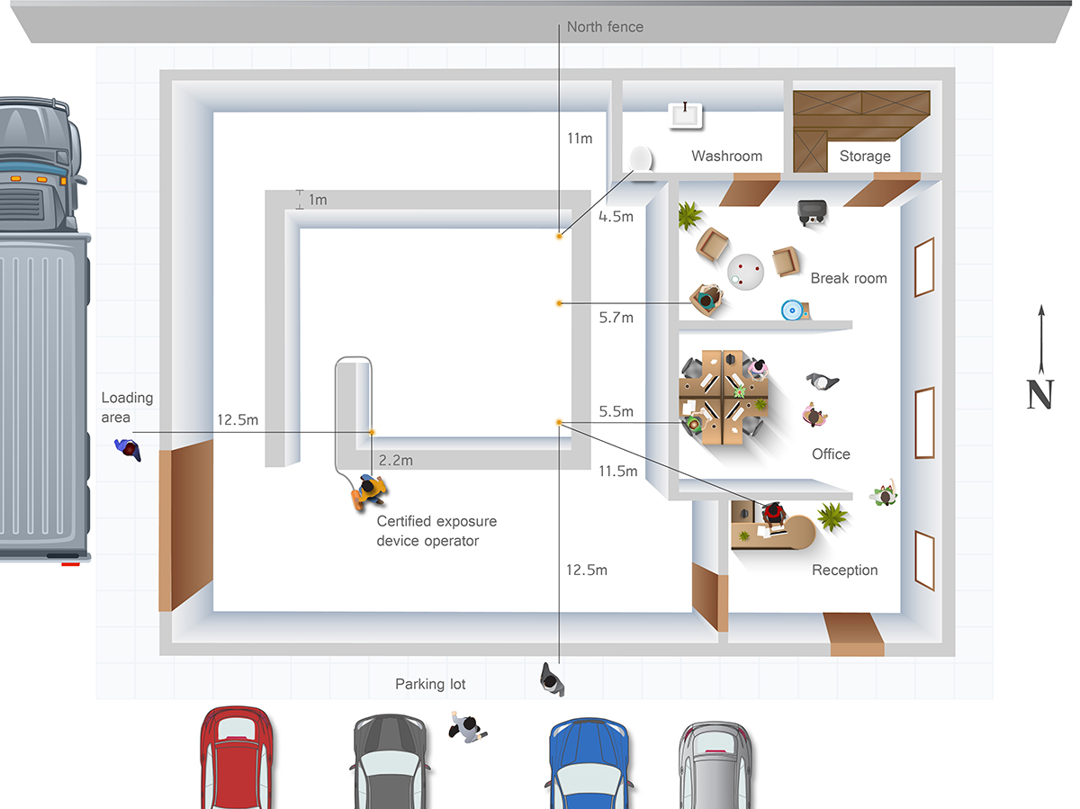
1. Drawing of the installation, the facility in which it’s located, and surrounding areas
Figure A1: The layout of the building showing the planned location of the radiography installation
2. Radiography installation information
The following information applies to this radiography installation:
- locations where the nuclear substances may be present is identified in Figure A1
- at this installation, a maximum of 20 radiography exposures per week are planned and operations will only take place during normal business hours (i.e., a maximum of 1040 exposures per year)
- the nuclear substance used for radiography at this installation is cobalt-60
- activity of the source is 4.07 TBq (110 Ci)
3. Identify the occupancy and the appropriate occupancy factor
Occupied locations were identified and occupancy factors were conservatively chosen. Information is summarized in Table A2.
| Location | T | Notes |
|---|---|---|
| CEDO’s position | 1 | There will be two full time workers that can perform radiography at this installation. The exact fraction of radiography exposures carried out by each exposure device operator is uncertain; as such, it is conservatively assumed that all of the exposures are carried out by one CEDO. |
| Receptionist desk | 1 | It is conservatively assumed that the receptionist will be occupying the receptionist desk for all radiography exposures. The receptionist is not a NEW. |
| Break room | 1/4 | |
| Washroom | 1/16 | |
| Office space | 1 | The location in the office space closest to the source is assumed to be occupied by worker that is not a NEW. |
| Parking lot | 1/8 | |
| North fence | 1 | Assume worst case occupancy to be conservative. |
| Loading area | 1/8 | Assume workers at the adjacent business will be parking their cars and smoking in the parking lot. |
| Roof | N/A | Access is restricted during radiography exposures. |
| Basement | N/A | There is no basement in the building. |
4. Estimate the radiation dose rates produced in each potentially occupied area
Assuming a concrete wall thickness of 1 m for all walls of the radiography installation, the shielding thickness is greater than the TVL1 of 305 mm. Therefore, equation 3 should be used to calculate the dose rate at each location (not including skyshine). The calculated dose rates using this method are provided in Table A3. Since it is possible for radiography to be carried out with the source in different spots within the radiography installation, the most conservative cases were assumed when determining the distance between the source and location. For example, for the distance between the source and the office space, it was assumed that radiography exposures would take place with the source position in the location of the radiography installation closest to the office space.
Table A3: Calculated dose rates for the most occupied locations around the radiography installation (not including skyshine)
Gamma ray dose constant at 1 m (Γ) = 305 µSv/h per GBq
Dose rate (R) = (Γ x A x 0.1 x 10-(t-TVL1)/TVL2) / d2
| Location | Γ (µSv/h per GBq) | A (GBq) | t (mm) | TVL1 (mm) | TVL2 (mm) | d (m2) | R (µSv/h) | |
|---|---|---|---|---|---|---|---|---|
| CEDO’s position | 305 | 4070 | 1000 | 305 | 211 | 2.2 | = | 13 |
| Receptionist desk | 305 | 4070 | 1000 | 305 | 211 | 11.5 | = | 0.48 |
| Break room | 305 | 4070 | 1000 | 305 | 211 | 5.7 | = | 1.9 |
| Washroom | 305 | 4070 | 1000 | 305 | 211 | 4.5 | = | 3.1 |
| Office space | 305 | 4070 | 1000 | 305 | 211 | 5.5 | = | 2.1 |
| Parking lot | 305 | 4070 | 1000 | 305 | 211 | 12.5 | = | 0.40 |
| North fence | 305 | 4070 | 1000 | 305 | 211 | 11 | = | 0.52 |
| Loading area | 305 | 4070 | 1000 | 305 | 211 | 12.5 | = | 0.40 |
5. Extrapolate dose rates to annual doses for the persons who may occupy each area
The projected workload at this radiography installation is a maximum of 1040 exposures per year (i.e., 20 exposures per week). It is assumed that exposures are not collimated and will take three minutes each (i.e., 0.05 h). Using equation 2 the estimated annual doses to individuals occupying each location of interest are provided in Table A.4.
| Location | N | T | R (µSv/h) | S (h) | D (µSv) | |
|---|---|---|---|---|---|---|
| CEDO’s position | 1040 | 1 | 13.0 | 0.05 | = | 680 |
| Receptionist desk | 1040 | 1 | 0.5 | 0.05 | = | 25 |
| Break room | 1040 | 1/4 | 1.9 | 0.05 | = | 25 |
| Washroom | 1040 | 1/16 | 3.1 | 0.05 | = | 10 |
| Office space | 1040 | 1 | 2.1 | 0.05 | = | 110 |
| Parking lot | 1040 | 1/8 | 0.4 | 0.05 | = | 2.6 |
| North fence | 1040 | 1 | 0.5 | 0.05 | = | 27 |
| Loading area | 1040 | 1/8 | 0.8 | 0.05 | = | 2.6 |
The annual dose estimate for the NEW (i.e., the CEDO) is well below the annual dose limit. The annual dose estimates to persons who are not NEWs, occupying the receptionist desk, office space and north fence, are also below the dose limit of 1 mSv/year prescribed in subsection 13(1) of the Radiation Protection Regulations and the dose limit 0.5 mSv/year prescribed in the subsection 30(6) of the Nuclear Substances and Radiation Devices Regulations. Therefore, no additional shielding is required to keep doses below dose limits.
In addition, the break room, washroom, parking lot, north fence, and loading area may be occupied by both NEWs and non-NEWs and annual dose estimates at these locations should be added to the doses calculated for NEWs and non-NEWs. The estimated annual dose to the NEW, including the annual dose from occupying the break room, washroom, parking lot, north fence, and loading area, is still well below dose limits. The estimated annual dose to the most exposed non-NEW (i.e., the office space worker), including the annual dose from occupying the break room, washroom, parking lot, north fence, and loading area, is also below the dose limits. Therefore, concrete shielding of 1 m is adequate to keep the estimated dose to the office worker below the dose limits. In addition to keeping doses below the dose limits, doses shall also be ALARA. Skyshine dose estimates should be made by calculation or direct measurement before radiography exposures are carried out. If it can be demonstrated that annual doses to workers and members of the public (including skyshine) are below dose limits and ALARA, it can be concluded that the design is adequate for protecting persons occupying areas surrounding the radiography installation.
Glossary
- as low as reasonably achievable (ALARA) (niveau le plus bas qu’il soit raisonnablement possible d’atteindre [ALARA])
- A principle of radiation protection that holds that exposures to radiation are kept as low as reasonably achievable, social and economic factors taken into account. Section 4 of the Radiation Protection Regulations stipulates licensee requirements with respect to ALARA.
- beam limiter (obturateur de faisceau)
- A radiation-shielding device, located at the working position of an exposure device, which is designed to reduce the radiation dose rate in directions other than the direction intended for use. The beam limiter may be designed to be used in conjunction with an exposure head or may incorporate an exposure head as an integral part of the device. Also called collimator.
- becquerel (Bq) (becquerel [Bq])
- The International System of Units (SI) unit of radioactivity. One becquerel (Bq) is the activity of a quantity of radioactive material in which one nucleus decays per second. In Canada, the Bq is used instead of the non-SI unit curie (Ci). 1 Bq = 27 µCi (2.7 x 10¹¹ Ci) and 1 Ci = 3.7 x 10¹⁰ Bq.
- certified exposure device operator (CEDO) (opérateur d’appareil d’exposition accrédité)
- A person who has the qualifications to safely operate industrial gamma radiography exposure devices anywhere in Canada and who is certified as such by the CNSC.
- collimator (collimateur)
- See beam limiter.
- exposure (exposition)
- See irradiation.
- exposure device (appareil d’exposition)
- A radiation device that is designed for carrying out gamma radiography, and includes any accessory to the device such as a sealed source assembly, a drive mechanism, a sealed source assembly guide tube and an exposure head. (Sources: Nuclear Substances and Radiation Devices Regulations; Packaging and Transport of Nuclear Substances Regulations, 2015)
- gamma radiation (rayonnement gamma)
- Penetrating electromagnetic radiation emitted from an atom’s nucleus. Also called gamma rays.
- gamma ray constant
- The dose rate at a specific distance from a given amount of a photon-emitting radionuclide. It is used to predict radiation exposure in terms of equivalent dose per unit of activity per unit distance.
- gigabecquerel (GBq)
- One billion (109) becquerels.
- half-value layer (HVL) (couche de demi-atténuation [CDA])
- The thickness of a shield or absorber (such as tungsten or lead) that reduces the amount of radiation to one half of its initial intensity. Also called half-value thickness.
- industrial radiography (gammagraphie industrielle)
- The use of certified exposure devices to conduct the non-destructive examination of the structure of welds, castings and building components. Also called gamma radiography.
- irradiation (irradiation)
- Exposure to radiation. Note: "exposure" is commonly used to describe radiation doses to people while "irradiation" is more often used for radiation doses to food or industrial objects.
- maze entrance
- An indirect path from the entrance of a radiography installation to the exposure area. Using a maze entrance ensures that there is at least one shielded wall between the exposure operator and the exposure area.
- microsievert (µSv) (microsievert [µSv])
- One one-millionth of a sievert.
- nuclear energy worker (NEW) (travailleur du secteur nucléaire [TSN])
- A person who is required, in the course of the person’s business or occupation in connection with a nuclear substance or nuclear facility, to perform duties in such circumstances that there is a reasonable probability that the person may receive a dose of radiation that is greater than the prescribed limit for the general public. (Source: Nuclear Safety and Control Act)
- occupancy factor (facteur d’occupation)
- The fraction of total time during which a radiation field is present at a particular location, for which any one individual would reasonably be expected to be present at that location. This factor (≤1) is multiplied by the total radiation dose at that location, to derive the maximum personal dose any single person would be expected to receive.
- operate (faire fonctionner)
- Includes, in respect of an exposure device, coupling the drive mechanism to the exposure device, uncoupling the drive mechanism from the exposure device, locking or unlocking the exposure device, and all activities involving the device that take place while the sealed source assembly is not locked inside the device in the fully shielded position. (Source: Nuclear Substances and Radiation Devices Regulations)
- sievert (Sv) (sievert [Sv])
- The International System of Units (SI) unit of equivalent dose and effective dose, equal to 1 joule/kilogram.
- radiography installation
- A shielded enclosure, cell or vault where radiography is performed.
- scatter radiation (rayonnement diffusé)
- Radiation that, during passage through a substance, has been changed in direction. It may also have been modified by a decrease in energy. Also called scattered radiation.
- skyshine
- Scattered radiation generated by radiation reflecting off air particles; it commonly occurs above a radiography installation with inadequate or no roof shielding.
- tenth-value layer (TVL) (couche d’atténuation au dixième [CAD])
- The thickness of a shield or an absorber that reduces the radiation level to 10 percent of its initial level.
References
- Canadian Nuclear Safety Commission (CNSC), G-129 rev.1, Keeping Radiation Exposures and Doses "As Low as Reasonably Achievable (ALARA)", Ottawa, 2004.
- International Commission on Radiological Protection, ICRP Publication 116, Ann. ICRP 40(2-5), Conversion Coefficients for Radiological Protection Quantities for External Radiation Exposures, Thousand Oaks, California, 2010.
- Nucleonica GmbH, Joint Evaluated Fission and Fusion File (JEFF) 3.1, Nucleonica Nuclear Science Portal (nucleonica.com), Version 3.0.49, Karlsruhe, Germany, 2014
- CNSC, REGDOC-2.12.3, Security of Nuclear Substances: Sealed Sources, Ottawa, 2013.
- American National Standards Institute, ANSI N43.3-2008, Installations Using Non-Medical X-Ray and Sealed Gamma Ray Sources, Energies Up To 10 MeV, Washington, D.C., 2008.
- National Council on Radiation Protection and Measurements, Report No. 151, Structural Shielding Design and Evaluation for Megavoltage X- and Gamma-Ray Radiotherapy Facilities, Bethesda, Maryland, 2005.
Additional Information
The following documents contain additional information that may be of interest to persons involved in the design of industrial radiography installations in Canada.
- Canadian Nuclear Safety Commission, Working Safely with Industrial Radiography, Ottawa, 2014.
- International Atomic Energy Agency, IAEA Safety Standards, Specific Safety Guide No. SSG-11, Radiation Safety in Industrial Radiography, Vienna, 2011.
- United States Nuclear Regulatory Commission, NUREG 1556, Consolidated Guidance about Materials Licensees – Volume 2, Program Specific Guidance about Industrial Radiography Licenses, Washington, 1998.
- ANSI, N43.10-2001, Safe Design and Use of Panoramic, Wet Source Storage Gamma Irradiators (Category IV) and Dry Source Storage Gamma Irradiators (Category II), 2001.
- National Council on Radiation Protection and Measurements (NCRP), Report No. 49, Structural Shielding Design and Evaluation for Medical Use of X Rays and Gamma Rays of Energies Up To 10 MeV, Bethesda, Maryland, 1976.
- NCRP, Report No. 147, Structural Shielding Design for Medical X-Ray Facilities, Bethesda, Maryland, 2004.
- Johnson, Thomas E. and Brian K. Birky, Health Physics and Radiological Health, 4th edition, Baltimore, Maryland, 2012.
- Oak Ridge National Laboratory, ORNL/RSIC-45, Specific Gamma-Ray Dose Constants for Nuclides Important to Dosimetry and Radiological Assessment, Oak Ridge National Laboratory, Oak Ridge, Tennessee, 1982.
- American Nuclear Society, Radiation Shielding, Richard E. Faw, J. Shultis, La Grange Park, Illinois, 2000.
Footnotes
- Footnote 1
-
For an example of an inverse square law calculator, see radprocalculator.com/InverseSquare.aspx
CNSC Regulatory Document Series
Facilities and activities within the nuclear sector in Canada are regulated by the Canadian Nuclear Safety Commission (CNSC). In addition to the Nuclear Safety and Control Act and associated regulations, these facilities and activities may also be requirements to comply with other regulatory instruments such as regulatory documents or standards.
Effective April 2013, the CNSC's catalogue of existing and planned regulatory documents has been organized under three key categories and twenty-five series, as set out below. Regulatory documents produced by the CNSC fall under one of the following series:
- 1.0 Regulated facilities and activities
- Series 1.1 Reactor facilities
- 1.2 Class IB facilities
- 1.3 Uranium mines and mills
- 1.4 Class II facilities
- 1.5 Certification of prescribed equipment
- 1.6 Nuclear substances and radiation devices
- 2.0 Safety and control areas
- Series 2.1 Management system
- 2.2 Human performance management
- 2.3 Operating performance
- 2.4 Safety analysis
- 2.5 Physical design
- 2.6 Fitness for service
- 2.7 Radiation protection
- 2.8 Conventional health and safety
- 2.9 Environmental protection
- 2.10 Emergency management and fire protection
- 2.11 Waste management
- 2.12 Security
- 2.13 Safeguards and non-proliferation
- 2.14 Packaging and transport
- 3.0 Other regulatory areas
- Series 3.1 Reporting requirements
- 3.2 Public and Aboriginal engagement
- 3.3 Financial guarantees
- 3.4 Commission proceedings
- 3.5 CNSC processes and practices
- 3.6 Glossary of CNSC terminology
Note: The regulatory document series may be adjusted periodically by the CNSC. Each regulatory document series listed above may contain multiple regulatory documents. For the latest list of regulatory documents, visit the CNSC's website.